VSORA

Making dreams come true

DOGMa - PARTICLE FILTER

To detect objects and the predict the individual object behaviour are the main elements of an autonomous vehicle’s detection system. As the name implies object detection is intended to localize and classify objects in the surrounding environment of the vehicle. Behaviour prediction is used to understand the dynamics of the objects in the surrounding environment and then to predict how they will behave in the future. This behaviour prediction is critical in the autonomous vehicle’s decision making and risk assessment. The quality of the autonomous vehicle behaviour is consequently directly related to how well these two stages can be done.

DOGMa stands for Dynamic Occupancy Grid Map. This is essentially a grid that is created based on the data from multiple sensors. Information about the probability of occupancy and velocity estimate is generated for each pixel. The velocity element allows for separation between static and dynamic objects. This type of map is used to gain a 360 degree understanding of the environment around the vehicle.

Particle Filter Implementation

The particle filter has been around for more than 20 years now, and is by now considered the established technique for nonlinear state estimation. The main reasons for this is the ability to handle severe nonlinearities and non-Gaussian noise – both elements that the traditional Kalman filter has problems with (the basic assumption of the Kalman filter family is that noise is Gaussian).

To process non-Gaussian noise typically a Monte Carlo-based approach is taken, and the particle filter typically can be used for for example, simultaneous localization and mapping (SLAM) as well as object tracking. The downside with particle filters is that they are computationally heavy. Over the years particle filters have been used for various vehicle centric activities like camera and laser based road following, object tracking, map-aided localization, threat assessments, traffic estimation and motion planning.

There are many articles written about the particle filter and its implementation, but for this use case we have focused on the following article: A Random Finite Set Approach for Dynamic Occupancy Grid Maps with Real-Time Application (https://arxiv.org/pdf/1605.02406.pdf)

This is an overview of how the implementation is done:

Particle Filter Block Diagram

KITTI Implementation

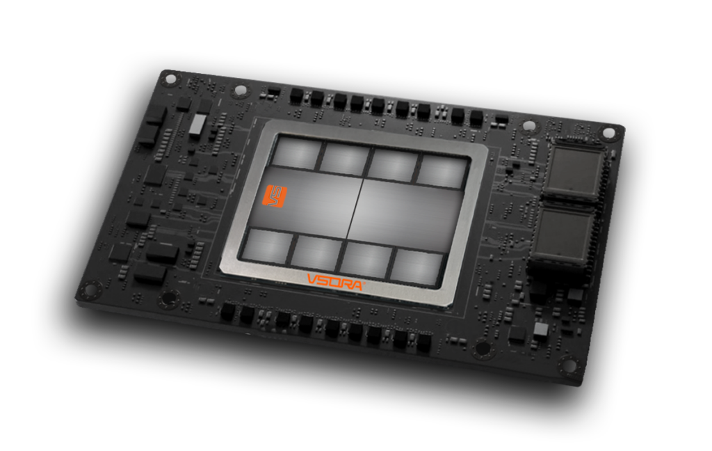
In this specific instance a particle filter (PF) with 4 million cells and 8 million particles has been implemented using the VSORA AD1028. Using a typical cell size of 10 x 10 cm this would represent a detection area of 100 meters in all directions around the ego vehicle.

The data is based on the KITTI database using a lidar pointcloud.

Current sensor technology typically provides new data every ~30 ms. During this time the environment needs to be analyzed and action decisions need to be taken and performed. Assuming that the time for decision and implementation will be ~1/3 of the available time, this leaves approx. 20 ms for the environmental analysis. There will be additional algorithms executed after the PF, and there may also be a need to do the analysis twice for safety purposes, so let’s assume that the available time to do a 4M PF analysis will be <10 ms. Is this possible given how compute heavy the implementation is?

The actual code used for the implementation is not extensive, and we have also included the GNSS data, so that we can maintain the compass direction fixed on the output (if required).

Below is an image showing the lidar pointcloud input and the 3D plot of the output.

Simulation Input / Output

Simulation Input / Output

Results

The referenced article contains results using a solution from another supplier (see link to article above). In our case we implemented an identical algorithm to what is being used in the article. As a side note it may be worth mentioning that there are ways to improve performance considerably.

The three main notable data points are:

Processing Capacity:4 Tflops
Latency:3.5 ms
Power per frame116 mJ

Looking For The Code?

3D Object Detection - PointPillars

One of the most important components of the perception system for autonomous vehicles is the 3D object detection. This is used to identify for example, vehicles, pedestrians, other obstacles and key features around the vehicle.

Most of the 3D object detection algorithms make use of a “bird’s eye” view of the vehicle, which may not be optimal for distinguishing important objects. After the computing the algorithms typically make anchor-based predictions of the locations and poses of the objects.

One of the most popular architectures using this approach is PointPillars. It makes use of learning representations built from birds-eye view pillars above the ground plane.

Below is a diagram of the PointPillars architecture that will be used for car detection.

PointPillars

KITTI Implementation

In this specific instance the implementation is based on lidar point cloud from the KITTI database using the VSORA AD1028. The result will be car detection in a 90 degree angle from the ego vehicle (80 meters to the right and 80 meters to the front). The cell size is 16 x 16 cm. The reference articles for this implementation are: The architecture was then broken down and the various components were allocated to either signal processing or AI compute units. The diagram below shows how this was done.

VSORA Task Separation

PointPillars Task Separation

Results

The referenced article contains results using a solution from another supplier (see link to article above). In our case we implemented an identical algorithm to what is being used in the article. As a side note it may be worth mentioning that there are ways to improve performance considerably.

The main notable data points are:

Latency (Full PointPillars):0.84 ms
Latency (AI only):0.24 ms

Looking For The Code?

Scroll to Top